Explosion Proof Hand Lamp with inline transformer - 220V AC to 24V DC - 10/50 Meter Cord
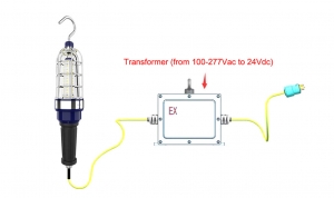
The CES-SC explosion-proof hand lamp is designed for use in hazardous environments where the presence of flammable gases, vapors, or dust particles may pose a risk of explosion. It is made of high-quality materials to ensure durability and safety, and is suitable for use in Class 1 Division 1 hazardous areas.
The body of the hand lamp is made of ADC12 aluminum alloy, which is a lightweight and strong material that can withstand high temperatures and impacts. The lamp is also fitted with a 10mm high-strength tempered glass lens (frosted, no glare), which provides excellent visibility while also protecting the bulb from damage.
To ensure safe operation, the hand lamp is equipped with an inline transformer and 10 or 50 meters (according to your requirement can be more longer) that steps down 120V AC to 24V AC or DC for powering the lamp. The hand lamp is designed to provide an effective low voltage lighting solution for operators requiring a versatile source of illumination.
In addition to its safety features, the explosion-proof hand lamp is also easy to carry and transport. Its compact size and lightweight design make it ideal for use in a variety of settings, from industrial sites to construction sites and inspection ,ect.
Overall, the explosion-proof hand lamp is a reliable and effective lighting solution for hazardous environments. Its high-quality construction, safety features, and portability make it an essential tool for anyone working in hazardous areas.
CUL for Hazloc:
- SUITABLE FOR WET LOCATIONS;
- THIS LUMINAIRE IS ACCEPTABLE FOR OPERATION IN AMBIENT CONDITIONS NOT EXCEEDING __55__ °C (_131 °F);
- MIN 90°C (194°F) SUPPLY CONDUCTORS;
- NO SERVICEABLE PARTS” OR “NO USER SERVICEABLE PARTS. DO NOT OPEN FOR CLEANING.;
- CAUTION - ″TO REDUCE THE RISK OF IGNITION OF HAZARDOUS ATMOSPHERES, DISCONNECT THE LUMINAIRE FROM THE SUPPLY CIRCUIT BEFORE OPENING. KEEP TIGHTLY CLOSED WHEN IN OPERATION.″;
- THIS PRODUCT MUST BE INSTALLED IN ACCORDANCE WITH THE APPLICABLE INSTALLATION CODE BY A PERSON FAMILIAR WITH THE CONSTRUCTION AND OPERATION OF THE PRODUCT AND THE HAZARDS INVOLVED;
- “CAUTION – RISK OF SHOCK” and “DISCONNECT POWER BEFORE SERVICING”.
Features
- Industry-leading efficacy: up to 130lm/W±5
- -40°C to +50°CCAmbient operating temperature
- Swivel hook for hanging and hands free operation
- Prevent drop damage
- 5 years warranty
- Housing –Aluminum alloy (ADC12 )
- Lens – tempered glass (10mm)
- Beam angle:360°
Parameters
- Power: 10W / 20W / 30W
- Input voltage: 100-240Vac; Frequency: 50/60Hz;
- Output voltage: 24Vdc
- Lumen flux: 1300LM/2600LM/3900LM
- CCT: 6500K (Optional)
- LEDs: 3030
- LED Driver: High Efficiency LED Driver
- Dimension: Φ101.5 x 516.5 mm
- Weight: 2.4KG
Certificate & Standard
Have certified CES-SC fixtures with the North American UL844 standards for hazardous location and environments.
NEC/CEC:
- Class I, Division 2, Groups A, B, C and D
- Class II, Division 1, Groups E, F and G
- Class I, Division 2, Groups A, B, C and D
- Class II, Division 2, Groups F and G
- Class III
- T-Class: T6 / T80°C
- Damp and wet locations
- Paint spray rated
- Certificate No:E475887
Standard:
- US: UL 844; UL 153;
- Canada: CSA C22.2 No. 137; CSA C22.2 No.250.4
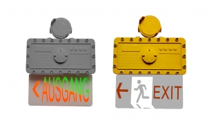
Hazardous Location Safety Exit Sign Ground Evacuation Indicator Light - Class 1 Division 2
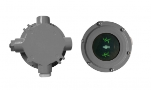
- Adpot to LEDs green-technology, energey saving, long lifespan.
- The housing is made of high-quality die-cast aluminum with anti-corrosion powder, which is corrosion-resistant and wear-resistant.
- It is suitable for indoors and outdoors where flammable gases or vapors or combustible dusts exist and create a hazardous locations and so on.
- Easy installation: Simplify the installation process, eliminate complex links, and make the installation project more convenient.
- AC100-277V 100-277V input voltage
Features
- Industry-leading efficacy: up to 120lm/W±5
- -40°C to +45°C / 50°C / 55°CAmbient operating temperature
- Wide optics for uniform illumination
- 5 years warranty
- Entry Size: M25Χ1.5 or NPT 3/4”-14
- Housing –Aluminum alloy (ADC12)
Parameters
- Power: 5 Watt
- Input voltage: AC100-277V, 50/60Hz
- Power factor: 0.97
- Lumen flux: 600lm
- CCT: 620-720K, Warm White
- Lamp type: LED (Bridgelux 3030 )
- LED Driver: High efficiency driver
- Emergency time: more than 90 min (1.5 hours)
Standard
Have certified CES-EX-BS-02 fixtures with with the North American UL844 standards for hazardous location and environments.
- Class I, Division 1 Groups C&D
- Class I, Division 2 Groups A,B,C,D
- Class II, Division 1 Groups E,F,G
- Class II, Division 2 Groups F&G
- Class III, Divisions 1 & 2
- Designed to UL 1598A, UL 844
- Suitable for Marine Use
- T6 Temperature Rating
Amounting
Versatile mounting options:
-
Customized
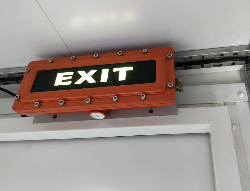
Explosion Proof LED Exit Sign - Class 1 Div 2 - 90 min Emergency Backup - Wall Mount
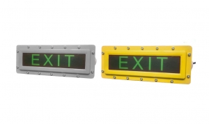
CES-EX-BS-02 Explosion Proof LED exit signs are designed for hazardous locations and are ideally suited for marking escape routes and exits in potentially explosive gas atmospheres or explosive dust atmospheres. This emergency LED Exit sign is available as an AC (100V - 270V) only version, but it is available with self-contained battery, no less than 90 min back up for emergency use.
Applications: In harsh and hazardous environments where illuminated exit signs are required.
Features:
- UL1598, 844, 924. IP 65, marine outside type
- Die-cast aluminum housing with anti-corrosion powder
- Long life (>50000 hours) for years of maintenance-free operation
- Energy-efficient for lower cost of operation
- Low temperature operation with no loss of illumination
- Rugged and durable light source for the harshest of environments
Features
- Industry-leading efficacy: up to 120lm/W±5
- -40°C to +45°C / 50°C / 55°CAmbient operating temperature
- Wide optics for uniform illumination
- 5 years warranty
- Entry Size: M25Χ1.5 or NPT 3/4”-14
- Housing –Aluminum alloy (ADC12)
Parameters
- Power: 5 Watt
- Input voltage: AC100-277V, 50/60Hz
- Power factor: 0.97
- Lumen flux: 600lm
- CCT: 620-720K, Warm White
- Lamp type: LED (Bridgelux 3030 )
- LED Driver: High efficiency driver
- Emergency time: more than 90 min (1.5 hours)
Standard
Have certified CES-EX-BS-02 fixtures with with the North American UL844 standards for hazardous location and environments.
- Class I, Division 1 Groups C&D
- Class I, Division 2 Groups A,B,C,D
- Class II, Division 1 Groups E,F,G
- Class II, Division 2 Groups F&G
- Class III, Divisions 1 & 2
- Designed to UL 1598A, UL 844
- Suitable for Marine Use
- T6 Temperature Rating
Amounting
Versatile mounting options:
-
Wall Mount
Explosion Proof Exit Sign - Class 1 Div 2 - 90 min Emergency Backup - Wall or Ceiling Mount
Description:
CES-EX-BS5 Led explosion proof emergency exit sign light is 5 Watt, has back up emergency ballast, it uses normal extermal power to iluminate 5 Watt led under normal conditions. In any situation where power is interrupted, I'll automatically switches to a battery backup model which will power for 90min or until power is restored. It rated for Class 1 Division 1&2, Class II Division 1&2, and is an ideal emergency exit marking solution for hazardous locations where fail safe reliability is a must.
Features
- Industry-leading efficacy: up to 120lm/W±5
- -40°C to +45°C /50°C /55°CAmbient operating temperature
- Wide optics for uniform illumination
- 5 years warranty
- Entry Size: M25Χ1.5 or NPT 3/4”-14
- Housing –Aluminum alloy (ADC12)
Parameters
- Power: 5 Watt
- Input voltage: AC100-277V, 50/60Hz
- Power factor: 0.97
- Lumen flux: 600lm/W
- CCT: 620-720K, Warm White
- Lamp type: LED (Bridgelux 3030 )
- LED Driver: High efficiency driver
- Emergency time: more than 90 min (1.5 hours)
Standard
Have certified CES-EX-BS fixtures with with the North American UL844 standards for hazardous location and environments.
- Class I, Division 1 Groups C&D
- Class I, Division 2 Groups A,B,C,D
- Class II, Division 1 Groups E,F,G
- Class II, Division 2 Groups F&G
- Class III, Divisions 1 & 2
- Designed to UL 1598A, UL 844
- Suitable for Marine Use
- T6 Temperature Rating
Amounting
Versatile mounting options:
-
Wall Mount / Pendant Ceiling Mount
Overview of ATEx and IECEx Certification
Equipment products certified by ATEX or IECEx are essential to be put into use in any potentially explosive or potentially explosive environments, and are an important guarantee to help create production safety. Most of us have heard of ATEX and IECEx certification, but many people sometimes still don't know the relationship between them. Let's introduce the relationship between the two certifications in detail.
IECEx explosion proof certification
International Electrotechnical Commission explosion-proof electrical product certification system (IEC Scheme for Certification to Standards for Electrical Equipment for Explosive atmospheres, hereinafter referred to as IECEx certification system) was established in 1996, is an international explosion-proof electrical product certification organization. Member countries of IECEx certification system include Australia, Canada, China, Denmark, Finland, France, Germany, Hungary, Italy, Japan, South Korea, Netherlands, Norway, New Zealand, Singapore, Romania, Serbia and Montenegro (formerly Yugoslavia), Russia, Slovenia , South Africa, Sweden, Switzerland, the United Kingdom and the United States 24, and are still increasing.
The goal of the IECEx system is to accept a standard worldwide ---- IEC/TC31 series of standards for electrical equipment for explosive hazardous environments; a certificate ---- IECEx certification certificate (IECEx Certification of Conformity); a mark -- -- IECEx certification mark (IECEx Mark of Conformity).
However, the explosion-proof products currently exported to EU countries only recognize the ATEX certificate, not the IECEx certificate. Some of the benefits of choosing a product with IECEx certification include:
(1) Increase market competitiveness. Products that have passed IECEx certification show that they have passed a series of tests of IEC60079 related standards and have reliable safety.
(2) Expand market circulation. At present, there are more than 50 member states of the IECEx system. Products used for IECEx certification can enter the market faster in these member states and shorten the time to market.
IECEx control products and main standards
The scope of IECEx controlled products is: pure electrical products/equipment used in explosion-proof environment, non-electrical products/equipment;
IECEx main standard: According to the difference in explosion-proof design of different equipment, it needs to be judged by professional and technical personnel. You can contact Eurotest for inquiries.
IECEx Certificate Overview
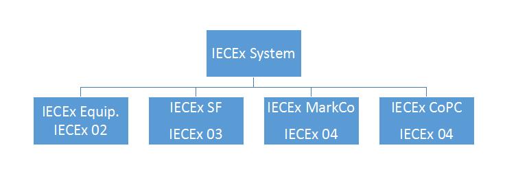
The IECEx certification system includes IECEx 02 product certification, IECEx 03 service certification, IECEx04 logo license, and IECEx05 personnel competency certification as shown in Figure as bellow,
IECEx Certificate System Component
IECEx Certificate System Component
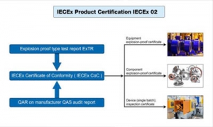
IECEx02 product certification stipulates that all explosion-proof products must meet the certification requirements. The certification process includes the applicant submitting the certification application, Ex TL conducting the explosion-proof type test, Ex CB conducting on-site inspection of the manufacturer's quality system, and Ex CB making the certification decision (issuing Ex TR and QAR), Ex CB issues the IECEx certification certificate, publishes it on the IECEx website, and Ex CB supervises the certified enterprise. Product certification is carried out in accordance with IECx OD003, IECEx OD009, IECEx OD017 and operation documents, and needs to meet the requirements of IEC 60079 series of technical standards. The quality system review of the manufacturer is carried out according to IEC OD005 operation documents. The simplified flow of certification procedures is shown in Figure

IECEx Certificate Flow Chart
IECEx03 service certification includes the audit of maintenance facilities, equipment and systems, confirmation of personnel's ability, and finally the generation of IECEx service certification. In order to meet the needs of the use department of Ex products for the quality certification of explosion-proof equipment repair and overhaul, the IECEx system began to launch IECEx service certification on the basis of explosion-proof product certification in 2003, including the factory or workshop certification plan for explosion-proof equipment repair and overhaul . In this regard, manufacturers of explosion-proof products can apply for IECEx service or choose to use manufacturers with IECEx system service certification.
The advantages of an explosion-proof product manufacturer applying for IECEx service include: it can prove the manufacturer's ability to repair explosion-proof products; if an explosion or fire occurs, it can resist liability lawsuits against the manufacturer for the repaired electrical equipment; it can ensure that explosion-proof products are in use consistency; enhances end-user confidence in purchasing products from explosion-proof product manufacturers. IECEx03 service certification is based on IECEx OD014 operation document, which puts forward specific requirements for the quality system, technical documents, facilities and equipment, and personnel of explosion-proof equipment repair factories; IECEx OD 013 operation document makes specific provisions for the review of Ex service certification; IEC60079 -19 made detailed requirements for specific content.
IECEx05 personnel competency certification provides proof that the knowledge and skills of personnel engaged in explosion-proof equipment and related personnel in explosive environments meet IECEx requirements, whether they have mastered safe operating procedures in hazardous locations, and whether they can correctly install, inspect, maintain and repair explosion-proof equipment and systems. . IECEx personnel competency assessment is carried out according to IECEx OD501, IECEx OD502, IECEx OD503, IECEx OD504 operation documents. The specific competency units are shown in Table 1. Each unit has clear requirements for personnel experience, knowledge and skills. Applicants need to have certain skills. Only after technical experience and training experience can you apply for evaluation. Unit 001 is the basic unit, and the unit must be based on 001 to apply for the evaluation of other units.
Table 1 Personnel competency certification components
|
No. |
Competency components |
|
1 |
Basic guidelines for applying explosion protection |
|
2 |
Zoning of hazardous locations |
|
3 |
Installation of explosion-proof equipment and wiring systems |
|
4 |
Maintenance of Explosive Atmosphere Equipment |
|
5 |
Overhaul and repair of explosion-proof equipment |
|
6 |
Testing of electrical installations related to explosive atmospheres |
|
7 |
Visual and general inspection of electrical installations in explosive atmospheres |
|
8 |
Detailed inspection of electrical installations in explosive atmospheres |
|
9 |
Design of Electrical Installations for Explosive Atmospheres |
|
10 |
Inspection of electrical installations in explosive atmospheres |
IECEx certification conducts international certification for explosion-proof electrical products in accordance with international standards, which can reduce the manufacturer's certification costs and time to enter the market on the premise of ensuring the appropriate safety level of explosion-proof electrical products, and maintain international standards in the process of product and service evaluation. And the service evaluation is included in an international database, which increases the user's trust in the manufacturer's or personnel's service, and has received extensive support from the industry and related parties in various countries.
Three main steps to obtain IECEx-COC explosion-proof certificate
- Obtaining IECEx-TR files;
- The factory has obtained the IECEx-QA explosion-proof system certificate;
- Register and record on IECEX official website to form IECEx-COC certificate.
Main classification of IECEx certificate
- Batch unit certification, that is, the IECEx certificate is only valid for this batch of products;
- COC type certification, that is, a specific type of product with a certain explosion-proof design meets the requirements of IECEx, and can be used for a long time under the condition that the IECEx system certificate is always valid;
- The IECEx explosion-proof system certificate is the QA certificate, which indicates that the certificate holder has the ability to control products that meet the requirements of the corresponding IECEx explosion-proof standards.
ATEX explosion-proof certification
The ATEX directive in CE certification is 2014/34/EU (the old directive 94/9/EC). ATEX is derived from the French "Atmosphere EXlposible". On March 23, 1994, the European Commission adopted "equipment and protection for potentially explosive environments. System" (94/9/EC) Directive. The Directive has been in use since 1996 and has been enforced since July 1, 2003.
This directive covers mine and non-mine equipment. Unlike previous directives, it includes mechanical equipment and electrical equipment, and extends the potentially explosive atmosphere to dust and flammable gases, flammable vapors and mists in the air. This directive is the "new approach" directive commonly referred to as ATEX 100A, the current ATEX explosion protection directive.
Manufacturers of equipment intended for use in potentially explosive atmospheres, applying the terms of the ATEX directive and affixing the CE mark, can sell their explosion-proof equipment anywhere in Europe without considering the application of additional requirements.
ATEX explosion-proof certification is a mandatory requirement for explosion-proof products to enter the EU market. Therefore, products used for explosive products entering the EU market must follow the ATEX directive, obtain ATEX certification, and affix the ATEX mark on the product.
|
Explosion-proof group classification |
|
|
Mining Group I |
Mining Group I |
|
Non-mining Group II |
Non-mining Group II |
|
Classification of explosion-proof areas |
|
|
Zone 0 (Gas) |
Areas where explosive atmospheres persist or occur frequently |
|
Zone 1 (Gas) |
When the equipment is in normal operation, the explosive environment exists or may exist for a long time, and the frequency is occasional |
|
Zone 2 (Gas) |
When the equipment is not operating normally, the explosive environment exists or may exist for a short period of time, and the frequency under normal circumstances is less likely to occur |
|
Zone 20 (dust) |
More than 1000 hours/year or more than 10%/cycle |
|
Zone 21 (dust) |
10~1000 hours/year or 0.1~10%/cycle |
|
Zone 22 (dust) |
Less than 10 hours/year or less than 0.1%/cycle |
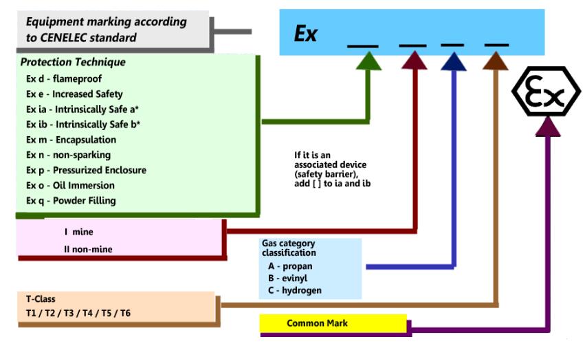
Explosion-proof categories, zones and markings
|
ATEX |
|||
|
Standard |
EN60079 |
||
|
|
Group |
Areas |
Ex-Proof Marking |
|
Coal Mine |
I |
Category M1( I M 1 ) |
Ex ia I |
|
Ex Ib I |
|||
|
Ex d I |
|||
|
Category M2( I M 2 ) |
Manufacturer's certificate |
||
|
Gas-Ex |
II |
Zone 0 ( II 1 G ) |
Ex ia II C/B/A |
|
Ex s |
|||
|
Zone 1 ( II 2 G ) |
EEx ia II C/B/A |
||
|
EEx s |
|||
|
EEx ib II C/B/A |
|||
|
EEx d II C/B/A |
|||
|
EEx e |
|||
|
EEx px, py |
|||
|
EEx o |
|||
|
EEx q |
|||
|
EEx m |
|||
|
EEx s |
|||
|
|
|||
|
Zone 2 ( II 3 G ) |
Suitable for all types of zones 0 and 1 |
||
|
EEx nA |
|||
|
EEx nC |
|||
|
EEx nL |
|||
|
EEx nR |
|||
|
EEx pz |
|||
|
|
|||
|
Standard |
EN50281 |
||
|
Dust-Ex |
III |
Zone 20 ( II 1 D ) |
Ex 1D |
|
Zone 21 ( II 2 D ) |
Ex 2D |
||
|
Zone 22 ( II 3 D ) |
Ex 3D |
||
Explosive Hazardous Gas Classification
|
Group |
ATEX |
Typical gas |
Ignition characteristics |
|
I |
I |
Methane |
From easy to difficult |
|
II |
II A |
propane |
|
|
II B |
vinyl |
||
|
II C |
hydrogen |
||
|
Acetylene |
T-Class Classification
|
Temperature Classification |
safe surface temperature |
Common Explosive Gases |
|
T1 |
Less than or equal to 450 ℃ |
46 kinds of hydrogen, acrylonitrile, etc. |
|
T2 |
Less than or equal to 300 ℃ |
47 kinds of acetylene, ethylene, etc. |
|
T3 |
Less than or equal to 200 ℃ |
36 kinds of gasoline, crotonaldehyde, etc. |
|
T4 |
Less than or equal to 135 ℃ |
6 kinds of acetaldehyde, tetrafluoroethylene, etc. |
|
T5 |
less than or equal to 100 ℃ |
carbon disulfide |
|
T6 |
less than or equal to 85 ℃ |
Ethyl nitrate and ethyl nitrite |
Introduction of common explosion-proof methods
|
Explosion-proof way |
EN Standard |
Description of explosion-proof method |
|
Ex d - Flameproof |
EN 60079-1 |
When the equipment is in normal operation, the components that can generate the detonation source are put into the explosion-proof enclosure. The explosion-proof enclosure can withstand the internal explosion pressure without loss, and can effectively prevent the explosion from spreading to the outside of the enclosure. |
|
Ex e - Increased Safety |
EN 60079-7 |
Through the design of the product, the detonation source that can generate hot surface or arc or spark can be eliminated, so as to achieve the purpose of explosion protection. |
|
Ex i - Intrinsically Safe |
EN 60079-11 |
Circuit energy is limited by related techniques so that sparks or hot surfaces from electrical energy in electrical equipment are not sufficient to detonate substances in explosive atmospheres. |
|
Ex m - Encapsulation |
EN 60079-18 |
The equipment or its part that may ignite the substances in the explosive atmosphere is sealed in a substance, and the equipment or its part is isolated from the substances in the explosive atmosphere, so as to achieve the purpose of explosion protection. |
|
Ex n - non-sparking |
EN 60079-15 |
The magic seal is used to prevent the flammable substances in the explosive environment from contacting the sparks or arcs generated by the equipment, and at the same time eliminate the hot surface generated by the equipment, so as to achieve the purpose of explosion-proof. |
|
Ex p - Pressurized Enclosure |
EN 60079-2 |
The equipment or components that will generate the detonation source are prevented from being contained in an enclosure. The enclosure is first filled with an inert gas to remove the flammable substances in it, and at the same time, by maintaining the pressure inside the enclosure, the entry of external flammable substances is prevented, thereby preventing the entry of flammable substances. To achieve the purpose of explosion-proof. |
|
Ex o - Oil Immersion |
EN 60079-6 |
Submerge the entire components of electrical equipment in a protective liquid so that substances in the explosive atmosphere cannot contact the hot surfaces or sparks of the equipment. |
|
Ex q - Powder Filling |
EN 60079-5 |
Bury the components of electrical equipment in sand so that substances in the explosive atmosphere cannot relieve hot surfaces or sparks of the equipment. |
ATEX Explosion-proof Marking(for reference only)
The main difference between ATEX certification and IECEx certification
Although both ATEX certification and IECEx certification describe the necessary requirements for equipment used in potentially hazardous and hazardous locations, they differ in some respects, the main difference being that ATEX certification is driven by laws and IECEx certification is driven by standards.
Another difference is that ATEX certification is only valid in the EU, while IECEx certification is accepted worldwide. Likewise, ATEX certification is required by law for all non-electrical and electrical equipment to be used in hazardous locations. However, IECEx certification is only required for electrical equipment in hazardous locations.
In terms of standards, it is not mandatory for ATEX certification to conform to the standard, but for IECEx certification, a third-party certification body is responsible for combining all aspects of manufacturing and design for public certification. In short, IECEx certification is stricter than ATEX certification in the handling of evidence during the certification process.
Another fundamental difference is how each guide is set up. The IECEx certification system is actually one of the four conformity assessment systems operated by the IEC. The IECEx certification system consists of four independent international certification parts, including the IECEx Certified Equipment Program, the IECEx Certified Service Program, the IECEx Certified Conformity Mark Licensing System and the IECEx Certified Qualified Persons Program. However, ATEX certification refers to two separate but related directives, as described above.
The following list illustrates the relationship
|
Content |
ATEX |
IECEx |
|
Scope of application |
European |
IECEx member countries (except North American countries) |
|
Is it mandatory |
Mandatory |
Non-Mandatory |
|
Executive standard |
IEC60079 |
IEC60079 |
|
Explosion-proof mark |
|
Printed Ex logo |
|
convert |
At present, ATEX certificates cannot be converted into certificates from other countries outside the EU |
IEC member countries (except North American countries) recognize the IECEx report, which can be directly converted into the explosion-proof certification of the local country, except that some countries need to do some local difference tests. |

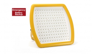
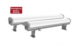
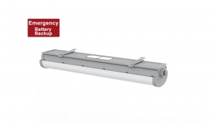
1ft 2ft Explosion Proof Emergency Light - 1.5 Hours Battery Backup
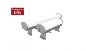
Destription:
The Explosion Proof Linear Fixture series features is a 90 minute emergency backup battery in 12W designed for hazardous environments where with explosive gas atmosphere or explosive dust atmosphere may be present.
This battery backup lighting fixtures made of the die-cast aluminum and the PC cover. Good heat, and 6J impact resistance.
Installation: pendant, ceiling, pole or more customized.
Adopt to the high light-efficacy LED source, up to 140lm/W, the CCT is 2700K, 3000K, 4000K, 5000K, 5700K, 6500K optional, no flicker, no glare.
The electrophoresis technology and the multiple coats of marine anti-corrosion paint, the all the mounting brackets and accessories are made of 316 stainless steel, UL1598A anti-corrosion standard can for marine location.
Warning :
- “CAUTION-USEFASTENER WITH YIELD STRESS ≥ 640 MPa”;
- “WARNING – DO NOT OPEN WHEN ENERGIZED”;
- “WARNING – DO NOT OPEN WHEN AN EXPLOSIVE ATMOSPHERE IS PRESENT”;
- “WARNING – ONLY USE CABLES SUITABLE FOR 85°C”;
- " WARNING - DETAILED TEMPERATURE CLASS - SEE INSTRUCTIONS”;
- “THE FLAMPROOF JOINTS ARE NOT INTENDED TO BE REPAIRED”;
- End user shall use certified cable gland or conduit with suitable type of protection for final installation purpose;
- External earthing wire shall be connected when used and the cross-sectional areashall be more than 4mm2 or 10AWG;
- Under rating condition, maximum temperature on the luminaire’s shell shall not be higher than 130℃ for T4.Temperature at cable inlet shall not be higher than allowable limit of the cable applied, to ensure the cable operation normally. The branch point is 83.6℃ and cable entry point is 69.4℃
Features
- Industry-leading efficacy: up to 140lm/W±5
- -40°C to +45°C /50°C /55°CAmbient operating temperature
- Wide optics for uniform illumination
- 5 years warranty
- Entry Size: M25Χ1.5 or NPT 3/4”-14
- Housing –Aluminum alloy (ADC12 )
- Lens – tempered glass (10mm)
- Beam angle: 120°
Parameters
- Power (1 Foot): 20W / 30W
- Power (2 Foot): 20W / 30W / 40W / 50W
- Input voltage: AC100-277V, 50/60Hz
- Power factor: 0.97
- Lumen flux: 2400LM - 6000LM
- CCT: 2700K - 6500K (Optional)
- LEDs: 3030 (6V)
- LED Driver: High efficiency driver
- Dimension: 329 mm x 125mm x 88.7 mm / 629 mm x 125mm x 88.7 mm
- Weight: 2.5KG (1 Feet), 3KG (2 Feet)
- Backup battery: Li-ion battery, 12W power
- Emergency: ≥ 1.5 hours
Amounting
Versatile mounting options:
- Ceiling mount (See Installation manual of CES-EX-LN-02P )
- Optional
- Mounting Angle:0°to ±90°;
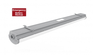
3ft 4ft Explosion Proof Emergency Light - 1.5 Hours Battery Backup
Description:
This 3ft 4ft Explosion Proof Linear Fixture series features a 90 minute emergency backup battery in 12W designed for hazardous environments where with explosive gas atmosphere or explosive dust atmosphere may be present.
This battery backup lighting fixtures made of the die-cast aluminum and the PC cover. Good heat, and 6J impact resistance.
Installation: pendant, ceiling, pole or more customized.
Adopt to the high light-efficacy LED source, up to 140lm/W, the CCT is 2700K, 3000K, 4000K, 5000K, 5700K, 6500K optional, no flicker, no glare.
The electrophoresis technology and the multiple coats of marine anti-corrosion paint, the all the mounting brackets and accessories are made of 316 stainless steel, UL1598A anti-corrosion standard can for marine location.
Warning
- “CAUTION-USEFASTENER WITH YIELD STRESS ≥ 640 MPa”;
- “WARNING – DO NOT OPEN WHEN ENERGIZED”;
- “WARNING – DO NOT OPEN WHEN AN EXPLOSIVE ATMOSPHERE IS PRESENT”;
- “WARNING – ONLY USE CABLES SUITABLE FOR 85°C”;
- " WARNING - DETAILED TEMPERATURE CLASS - SEE INSTRUCTIONS”;
- “THE FLAMPROOF JOINTS ARE NOT INTENDED TO BE REPAIRED”;
- End user shall use certified cable gland or conduit with suitable type of protection for final installation purpose;
- External earthing wire shall be connected when used and the cross-sectional areashall be more than 4mm2 or 10AWG;
- Under rating condition, maximum temperature on the luminaire’s shell shall not be higher than 130℃ for T4.Temperature at cable inlet shall not be higher than allowable limit of the cable applied, to ensure the cable operation normally. The branch point is 83.6℃ and cable entry point is 69.4℃
Features
- Industry-leading efficacy: up to 140lm/W±5
- -40°C to +45°C /50°C /55°CAmbient operating temperature
- Wide optics for uniform illumination
- 5 years warranty
- Entry Size: M25Χ1.5 or NPT 3/4”-14
- Housing –Aluminum alloy (ADC12 )
- Lens – PC cover
- Beam angle: 120°
Parameters
- Power (1 Foot): 40W / 50W / 60W / 70W
- Power (2 Foot): 40W / 50W / 60W / 70W / 80W / 100W
- Input voltage: AC100-277V, 50/60Hz
- Power factor: 0.97
- Lumen flux: 4800LM - 12000LM
- CCT: 2700K - 6500K (Optional)
- LEDs: 3030 (6V)
- LED Driver: High efficiency driver
- Dimension: 929 mm x 125mm x 88.7 mm / 1235mm x 155mm x 148mm
- Weight: 4.5KG (3 Feet), 5.5KG (4 Feet)
- Backup battery: Li-ion battery, 12W power
- Emergency: ≥ 1.5 hours
Amounting
Versatile mounting options:
- Ceiling mount (See Installation manual of CES-EX-LN-02P )
- Optional
- Mounting Angle:0°to ±90°;
4ft Class 1 Division 2 Emergency Linear Lights - 90 min backup battery
Description:
CES-EX-LN-02P-E series 4ft length emergency explosion proof linear LED fixtures, 40W, 50W, 60W, 65W, 70W, 75W power, with an backup ( 12 Watt ) Li-ion battery that provides energy efficient illumination, the emergency backup provide 1680 lumens for the 1.5 hours.
This linear hazardous location LED fixtures on only obtained UL844 certificate, can used for the hazard location of Class 1 Div 2 Groups A, B, C and D. For design and structure, this emergency hazardous location LED fixtures made of the die-cast aluminum and the PC cover. Good heat, and 6J impact resistance.
In addition, we designed this fixtures for marine location ( UL1598A certificate), we adopt to the electrophoresis technology and the multiple coats of marine anti-corrosion paint, the all the mounting brackets and accessories are made of 316 stainless steel, UL1598A anti-corrosion standard can for marine location.
For the optics, adopt to the high light efficacy LED source, up to 140lm/W, the CCT 2700K, 3000K, 4000K, 5000K, 5700K, 6500K optional, no flicker, no glare.
If you need IECEx and ATEx certified, please visit to 4ft emergency epxlosion proof linear lights of Zone 1.
CUL for Hazloc:
- SUITABLE FOR WET LOCATIONS;
- THIS LUMINAIRE IS ACCEPTABLE FOR OPERATION IN AMBIENT CONDITIONS NOT EXCEEDING __55__ °C (_131 °F);
- MIN 90°C (194°F) SUPPLY CONDUCTORS;
- NO SERVICEABLE PARTS” OR “NO USER SERVICEABLE PARTS. DO NOT OPEN FOR CLEANING.;
- CAUTION - ″TO REDUCE THE RISK OF IGNITION OF HAZARDOUS ATMOSPHERES, DISCONNECT THE LUMINAIRE FROM THE SUPPLY CIRCUIT BEFORE OPENING. KEEP TIGHTLY CLOSED WHEN IN OPERATION.″;
- THIS PRODUCT MUST BE INSTALLED IN ACCORDANCE WITH THE APPLICABLE INSTALLATION CODE BY A PERSON FAMILIAR WITH THE CONSTRUCTION AND OPERATION OF THE PRODUCT AND THE HAZARDS INVOLVED;
- “CAUTION – RISK OF SHOCK” and “DISCONNECT POWER BEFORE SERVICING”.
Features
- Industry-leading efficacy: up to 110 - 130lm/W
- -40°C to + 50°C Ambient operating temperature
- Mounting: Ceiling
- 5 years warranty
- Entry Size: NPT 3/4”-14
- Housing –Aluminum alloy (ADC12 and 6063 )
- Lens – Polycarbonate (PC)
- Beam angle:120°
Parameters
- Power: 40W / 50W / 60W / 65W / 75W
- Input voltage: AC100-240/277V, 50/60Hz
- Power factor: 0.97
- Lumen flux: 4800LM / 6000LM / 7200LM / 7800LM / 9000LM
- CCT: 2700K - 6500K (Optional)
- LEDs: 3030 (6V)
- LED Driver: high Efficiency LED Driver
- Dimension: 1229 mm x 138.3mm x 98.1 mm
- Weight: 5.5KG
- Backup battery: Li-ion battery, 12W power
- Emergency: ≥90 mins
Certificate & Standard
Have certified CES-EX-LN-02P fixtures with the North American UL844 standards for hazardous location and environments.
NEC/CEC:
- Class I, Division 2, Groups A, B, C and D
- T-Class: T4A / T5
- Damp and wet locations
- Certify No:E475887
Standard:
- US: UL 844; UL 1598;
- Canada: CSA C22.2 No. 137; CSA C22.2 No. 250.0
Special order
- Special Orders- Requirements
Contact us for special requirements
Tel: +86-755-83509822
Fax: +86-755-83509868
Email: This email address is being protected from spambots. You need JavaScript enabled to view it.
Email: This email address is being protected from spambots. You need JavaScript enabled to view it.
2ft Class 1 Division 2 Emergency Linear Lights - 90 min backup battery
Description:
CES-EX-LN-02P-E series 2ft length emergency explosion proof linear LED fixtures with an backup Li-ion battery that provides energy efficient illumination, the emergency backup provide 1680 lumens for the 1.5 hours.
This linear hazardous location LED fixtures on only obtained UL844 certificate, can used for the hazard location of Class 1 Div 2 Groups A, B, C and D. For design and structure, this emergency hazardous location LED fixtures made of the die-cast aluminum and the PC cover. Good heat, and 6J impact resistance.
In addition, we designed this fixtures for marine location ( UL1598A certificate), we adopt to the electrophoresis technology and the multiple coats of marine anti-corrosion paint, the all the mounting brackets and accessories are made of 316 stainless steel, UL1598A anti-corrosion standard can for marine location.
For the optics, adopt to the high light efficacy LED source, up to 140lm/W, the CCT 2700K, 3000K, 4000K, 5000K, 5700K, 6500K optional, no flicker, no glare.
If you need IECEx and ATEx certified, please visit to 2ft emergency epxlosion proof linear lights of Zone 1.
CUL for Hazloc:
- SUITABLE FOR WET LOCATIONS;
- THIS LUMINAIRE IS ACCEPTABLE FOR OPERATION IN AMBIENT CONDITIONS NOT EXCEEDING __55__ °C (_131 °F);
- MIN 90°C (194°F) SUPPLY CONDUCTORS;
- NO SERVICEABLE PARTS” OR “NO USER SERVICEABLE PARTS. DO NOT OPEN FOR CLEANING.;
- CAUTION - ″TO REDUCE THE RISK OF IGNITION OF HAZARDOUS ATMOSPHERES, DISCONNECT THE LUMINAIRE FROM THE SUPPLY CIRCUIT BEFORE OPENING. KEEP TIGHTLY CLOSED WHEN IN OPERATION.″;
- THIS PRODUCT MUST BE INSTALLED IN ACCORDANCE WITH THE APPLICABLE INSTALLATION CODE BY A PERSON FAMILIAR WITH THE CONSTRUCTION AND OPERATION OF THE PRODUCT AND THE HAZARDS INVOLVED;
- “CAUTION – RISK OF SHOCK” and “DISCONNECT POWER BEFORE SERVICING”.
Features
- Industry-leading efficacy: up to 110 - 130lm/W
- -40°C to + 50°C Ambient operating temperature
- Mounting: Ceiling
- 5 years warranty
- Entry Size: NPT 3/4”-14
- Housing –Aluminum alloy (ADC12 and 6063 )
- Lens – Polycarbonate (PC)
- Beam angle:120°
Parameters
- Power: 30W / 40W / 50W
- Input voltage: AC100-240/277V, 50/60Hz
- Power factor: 0.97
- Lumen flux: 2600LM / 4800LM / 6000LM
- CCT: 2700K - 6500K (Optional)
- LEDs: 3030 (6V)
- LED Driver: high Efficiency LED Driver
- Dimension: 629 mm x 125mm x 88.7 mm
- Weight: 3.0KG
- Backup battery: Li-ion battery, 12W power
- Emergency: ≥90 mins
Certificate & Standard
Have certified CES-EX-LN-02P fixtures with the North American UL844 standards for hazardous location and environments.
NEC/CEC:
- Class I, Division 2, Groups A, B, C and D
- T-Class: T4A / T5
- Damp and wet locations
- Certify No:E475887
Standard:
- US: UL 844; UL 1598;
- Canada: CSA C22.2 No. 137; CSA C22.2 No. 250.0
Special order
- Special Orders- Requirements
Contact us for special requirements
Tel: +86-755-83509822
Fax: +86-755-83509868
Email: This email address is being protected from spambots. You need JavaScript enabled to view it.
Email: This email address is being protected from spambots. You need JavaScript enabled to view it.
Explosion Proof Emergency Lighting - 1.5 Hours - 120W/150W/180W/200W