
Arrangement of Hazardous Plants and Warehouses

Part 1: General floor plan
- Class A and B workshops and warehouses with explosion hazard should be set up independently, and should be open or semi-open, and the load-bearing structure should be reinforced concrete or steel frame, bent frame structure.
- The layout of the factory building with the danger of explosion should preferably be rectangular, which should be perpendicular to the dominant wind direction or the included angle should not be less than 45°, so as to effectively use the wind through the hall to disperse the explosive gas.
- The explosion-proof workshop should be set up separately. If it must be adjacent to the non-explosion-proof workshop, it can only be adjacent to one side, and the two should be separated by a firewall or an explosion-proof wall. There should be no direct communication between two adjacent workshops to avoid the impact of explosion shock waves.
Part. 2: Plane and Spatial Arrangement
- Main control room and sub-control room
1) The general control room of Class A and B workshops with explosion hazard shall be set up independently.
2) The sub-control rooms of Class A and B workshops with explosion hazard should be set up independently. When set adjacent to the outer wall, a fire partition wall with a fire resistance rating of not less than 3.00h should be used to separate them from other parts.
- Parts with explosion hazard
1) Class A and B production sites with explosion hazard should be arranged near the pressure relief facilities near the outer wall of the single-storey factory building or the pressure relief facilities on the top floor of the multi-storey factory building near the outer wall.
2) The equipment with the danger of explosion should avoid the main load-bearing components such as beams and columns in the workshop.
3) Protective measures such as door buckets should be installed in the stairwells, outdoor stairs in the explosion-hazardous area, or the connection between the explosion-hazardous area and the adjacent area. The partition wall of the door bucket should be a fire partition wall with a fire resistance rating of not less than 2.00h, and the door should be a Class A fire door and should be staggered from the door of the stairwell.
- Plants that emit flammable gas and flammable vapor
1) For Class A workshops that emit flammable gas and flammable vapor lighter than the air, light roof panels should be used as the pressure relief area. The ceiling should be as flat as possible without dead ends, and the upper space of the workshop should be well ventilated.
2) Class A workshops that emit flammable gases and flammable vapors heavier than air and Class B workshops that have the danger of dust and fiber explosion shall meet the following requirements:
A non-sparking ground should be used. When using insulating material as the overall surface layer, anti-static measures should be taken.
For workshops that emit combustible dust and fibers, the inner surface should be flat, smooth and easy to clean.
It is not advisable to set trenches in the workshop. When it is really necessary, the cover should be tight. The trenches should take effective measures to prevent the accumulation of combustible gas, combustible vapor, dust and fibers in the trenches, and should be sealed with fireproof materials at the connection with the adjacent workshop.
- Plants and warehouses that use, produce or store Class A, B and C liquids
1) For workshops that use and produce Class A, B and C liquids, the pipes and trenches should not be connected with those of the adjacent workshops, and oil separation facilities should be set up in the sewers.
2) Class A, B, and C liquid warehouses should be equipped with facilities to prevent liquid from spreading. Measures to prevent water immersion should be taken in the warehouse of goods that will burn and explode when wet.
- Underground and semi-basement
1) Class A and B production sites should not be set up underground or semi-underground.
2) Class A and B warehouses should not be set up underground or semi-underground.
The intrinsically safe system is a circuit system that achieves electrical explosion-proof by limiting electrical energy, and does not restrict the use of places (where the ia level is applicable to dangerous places in Zone 0, Zone I, and Zone II) and explosive The type of gas mixture (limited to include all flammable gases); with a high degree of safety, maintainability and economy. A schematic diagram of an intrinsically safe system.
Part 3 Pressure Relief
- Pressure relief facilities should be set up in the workshop with explosion hazard or in the part with explosion hazard in the workshop.
- The pressure relief facilities should use lightweight roof panels, lightweight walls, doors and windows that are easy to relieve pressure, etc., and materials such as safety glass that do not produce sharp fragments during explosion should be used.
- The pressure relief facilities should be set away from crowded places and main traffic roads, and should be close to the parts with danger of explosion.
- The mass of lightweight roof panels and walls used as pressure relief facilities should not be greater than 60kg/㎡. The pressure relief facility on the roof should take measures to prevent the accumulation of ice and snow.
- For Class A workshops that emit flammable gas and flammable vapor lighter than the air, light roof panels should be used as the pressure relief area. The ceiling should be as flat as possible without dead ends, and the upper space of the workshop should be well ventilated.
Part 4 Calculation pf Pressure Relief Area
Calculation formula of pressure relief area:
A=10CV2/3
A--pressure relief area (㎡);
V--the volume of the workshop (m³);
C - pressure relief ratio
1) Length-to-diameter ratio: the ratio of the product of the longest dimension in the geometric dimensions of the building and its cross-sectional perimeter to 4.0 times the cross-sectional area of the building.
2) When the aspect ratio of the factory building is greater than 3, the building should be divided into multiple calculation sections with an aspect ratio not greater than 3, and the common section in each calculation section shall not be used as a pressure relief area.
Explosion Proof LED Work Light - 180 Beam Angle - 30W
This explosion proof work light is LED type, 30 watt can replace to the traditional fluorescent lamps, 180 beam angle of optics design, rated for Zone 2 &22, and it's ideal for general work activities in hazardous location requiring explosion proof protection. In addition, this hand light’s lighting effects are particular good in the horizontal and vertical plane, no glare, no flicker, to improve the safety of the working at night.
Structure & Material
Patent structure design, explosion proof aluminum alloy, good heat dissipation.IP65 protection rated, lasting and reliable.
Glass: Tempered, 78% Transmittance, shock & vibration resistant.
Power Driver: Meanwell HLG Series, 90% driver efficacy.
Light efficacy up to 90lm/W. Optimize illumination in vertical plane.
No glare to ensure a comfortable.
Up to 80% energy save renovation solution.
Parameters
Power: 30WVoltage: 100-277V, 50-60 Hz
Power Factor: >0.95 @277V
THD: <15%
Operating Temperature: -40℃<Ta<50℃
Color Temperature: 2700-6500K
Luminous Efficacy: 120±5 lm/W
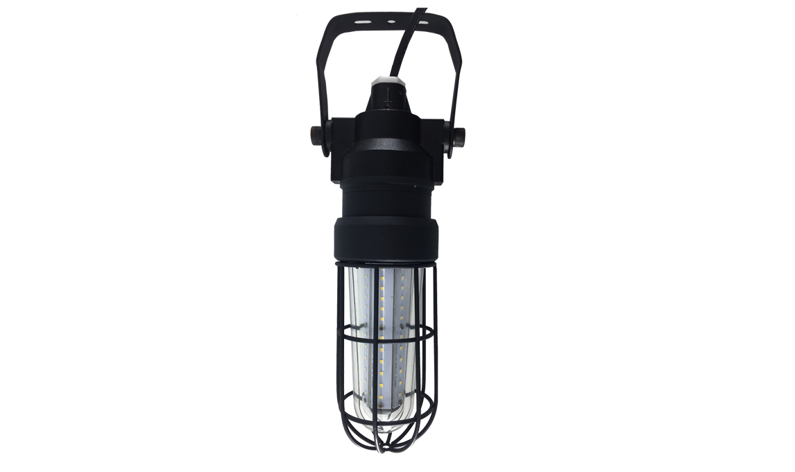
Explosion Proof LED Drop Light - 360 Beam Angle - 30W
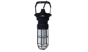
This 360 beam angle explosion proof drop light is LED type, 30 watt can replace to the traditional fluorescent lamps, 360 beam angle of optics design, rated for Zone 2 &22, and it's ideal for general work activities in hazardous location requiring explosion proof protection. In addition, this hand light’s lighting effects are particular good in the horizontal and vertical plane, no glare, no flicker, to improve the safety of the working at night.
Structure & Material
Patent structure design, explosion proof aluminum alloy, good heat dissipation.IP65 protection rated, lasting and reliable.
Glass: Tempered, 78% Transmittance, shock & vibration resistant.
Power Driver: Meanwell HLG Series, 90% driver efficacy.
Light efficacy up to 90lm/W. Optimize illumination in vertical plane.
No glare to ensure a comfortable.
Up to 80% energy save renovation solution.
Parameters
Power: 30WVoltage: 100-277V, 50-60 Hz
Power Factor: >0.95 @277V
THD: <15%
Operating Temperature: -40℃<Ta<50℃
Color Temperature: 2700-6500K
Luminous Efficacy: 120±5 lm/W
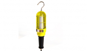
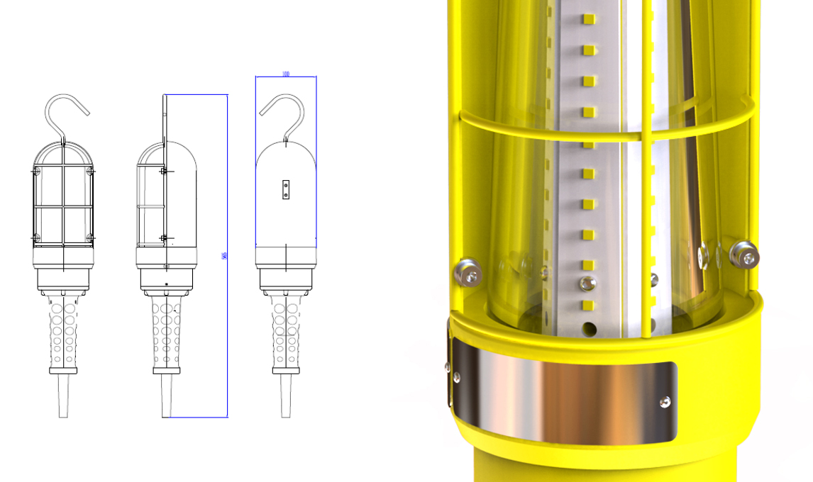
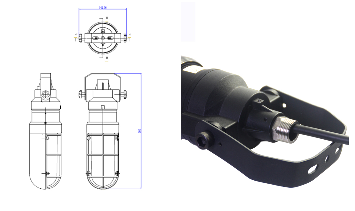
Explosion Proof LED Drop Light - 180 Beam Angle - 30W
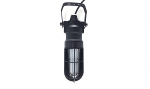
CESP portable LED explosion proof drop light (explosion proof hand lamp ) is 30W, rated for Zone 2 Zone 22, and it's ideal for general work activities in hazardous location requiring explosion proof protection. In addition, this hand lamp’s lighting effects are particular good in the horizontal and vertical plane, no glare, no flicker, to improve the safety of the working at night.
Structure & Material
Patent structure design, explosion proof aluminum alloy, good heat dissipation.IP65 protection rated, lasting and reliable.
Glass: Tempered, 78% Transmittance, shock & vibration resistant.
Power Driver: Meanwell HLG Series, 90% driver efficacy.
Light efficacy up to 90lm/W. Optimize illumination in vertical plane.
No glare to ensure a comfortable.
Up to 80% energy save renovation solution.
Parameters
Power: 30WVoltage: 100-277V, 50-60 Hz
Power Factor: >0.95 @277V
THD: <15%
Operating Temperature: -40℃<Ta<50℃
Color Temperature: 2700-6500K
Luminous Efficacy: 120±5 lm/W
Explosion Proof LED Light - Zone 1 - Round
Application
- Wastewater treatment, oil and gas refineries, drilling rigs, petrochemical facilities, food and beverage facilities, tunnels, outdoor or indoor mounted general area lighting, and where flammable vapors, gases, ignitable dusts, fibers or flyings are present.
Standard
ATEX: EN IEC 60079-0-2018; EN 60079-7-2015; EN 60079-18-2015; EN 60079-31-2014;
Warning
ATEX :
- “WARNING – DO NOT OPEN WHEN ENERGIZED”;
- “WARNING – DO NOT OPEN WHEN AN EXPLOSIVE ATMOSPHERE IS PRESENT”;
- “WARNING – POTENTIAL ELECTROSTATIC CHARGING HAZARD – SEE INSTRUCTION”;
- End user shall use certified cable gland suitable type of protection for final installation purpose;
- The end user should be able to ensure that the product is not affected by the risk of static electricity.
- External earthing wire shall be connected when used and the cross-sectional area shall be more than 4mm²or 10AWG;
- Under rating condition, maximum temperature on the luminaire’s shell shall not be higher than 128℃ for T4.Temperature at cable inlet shall not be higher than allowable limit of the cable applied, to ensure the cable operation normally. The branch point is 51.4℃ and cable entry point is 47.3℃
Features
- Industry-leading efficacy: up to 140 lm/W
- -40°C to +40°C Ambient operating temperature
- Wide optics for uniform illumination
- 5 years warranty
- Entry Size: PG9
- Housing – Aluminum alloy (ADC12 )
- Lens – tempered glass
- Beam angle: 98°
- Dimension: 419 × 274 × 99.4mm
- Weight: 2.8kg
Parameters
- Power: 20W / 30W / 40W / 50W / 60W
- Input voltage: AC100-240/277V, 50/60Hz
- Power factor: 0.97
- Light efficacy: 120 - 140lm/W
- CCT: 3000K/4000K/5000K/5700K/6500K
- LEDs: 3030
- LED Driver: High efficiency LED Driver
Certificate & Standard
- II 2G Ex db eb IIC T4 Gb;
- II 2D Ex tb IIIC T 128°C Db;
- IP66;
- Certificate No:SEV 20 ATEX 0412X;
Mounting
Versatile mounting options:
- Pole mount
- Wall mount
- Ceiling mount
- U-bracket
- Drop mount
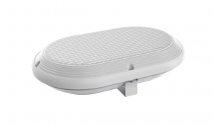
Explosion Proof LED Light - Zone 1 - Ellipse
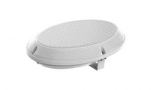
Application
- Wastewater treatment, oil and gas refineries, drilling rigs, petrochemical facilities, food and beverage facilities, tunnels, outdoor or indoor mounted general area lighting, and where flammable vapors, gases, ignitable dusts, fibers or flyings are present.
Standard
ATEX: EN IEC 60079-0-2018; EN 60079-7-2015; EN 60079-18-2015; EN 60079-31-2014;
Warning
ATEX :
- “WARNING – DO NOT OPEN WHEN ENERGIZED”;
- “WARNING – DO NOT OPEN WHEN AN EXPLOSIVE ATMOSPHERE IS PRESENT”;
- “WARNING – POTENTIAL ELECTROSTATIC CHARGING HAZARD – SEE INSTRUCTION”;
- End user shall use certified cable gland suitable type of protection for final installation purpose;
- The end user should be able to ensure that the product is not affected by the risk of static electricity.
- External earthing wire shall be connected when used and the cross-sectional area shall be more than 4mm²or 10AWG;
- Under rating condition, maximum temperature on the luminaire’s shell shall not be higher than 128℃ for T4.Temperature at cable inlet shall not be higher than allowable limit of the cable applied, to ensure the cable operation normally. The branch point is 51.4℃ and cable entry point is 47.3℃
Features
- Industry-leading efficacy: up to 140 lm/W
- -40°C to +40°C Ambient operating temperature
- Wide optics for uniform illumination
- 5 years warranty
- Entry Size: PG9
- Housing – Aluminum alloy (ADC12 )
- Lens – tempered glass
- Beam angle: 98°
- Dimension: 419 × 274 × 99mm
- Weight: 2.8kg
Parameters
- Power: 20W / 30W / 40W / 50W / 60W
- Input voltage: AC100-240/277V, 50/60Hz
- Power factor: 0.97
- Light efficacy: 120 - 140lm/W
- CCT: 3000K/4000K/5000K/5700K/6500K
- LEDs: 3030
- LED Driver: High efficiency LED Driver
Certificate & Standard
- II 2G Ex db eb IIC T4 Gb;
- II 2D Ex tb IIIC T 128°C Db;
- IP66;
- Certificate No:SEV 20 ATEX 0412X;
Mounting
Versatile mounting options:
- Pole mount
- Wall mount
- Ceiling mount
- U-bracket
- Drop mount
Explosion Proof LED Light - Zone 1 - Square
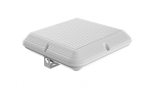
Application
- Wastewater treatment, oil and gas refineries, drilling rigs, petrochemical facilities, food and beverage facilities, tunnels, outdoor or indoor mounted general area lighting, and where flammable vapors, gases, ignitable dusts, fibers or flyings are present.
Standard
ATEX: EN IEC 60079-0-2018; EN 60079-7-2015; EN 60079-18-2015; EN 60079-31-2014;
Warning
ATEX :
- “WARNING – DO NOT OPEN WHEN ENERGIZED”;
- “WARNING – DO NOT OPEN WHEN AN EXPLOSIVE ATMOSPHERE IS PRESENT”;
- “WARNING – POTENTIAL ELECTROSTATIC CHARGING HAZARD – SEE INSTRUCTION”;
- End user shall use certified cable gland suitable type of protection for final installation purpose;
- The end user should be able to ensure that the product is not affected by the risk of static electricity.
- External earthing wire shall be connected when used and the cross-sectional area shall be more than 4mm²or 10AWG;
- Under rating condition, maximum temperature on the luminaire’s shell shall not be higher than 128℃ for T4.Temperature at cable inlet shall not be higher than allowable limit of the cable applied, to ensure the cable operation normally. The branch point is 51.4℃ and cable entry point is 47.3℃
Features
- Industry-leading efficacy: up to 140 lm/W
- -40°C to +40°C Ambient operating temperature
- Wide optics for uniform illumination
- 5 years warranty
- Entry Size: PG9
- Housing – Aluminum alloy (ADC12 )
- Lens – tempered glass
- Beam angle: 98°
- Dimension: 419×271×99mm
- Weight: 2.8kg
Parameters
- Power: 20W / 30W / 40W / 50W / 60W
- Input voltage: AC100-240/277V, 50/60Hz
- Power factor: 0.97
- Light efficacy: 120 - 140lm/W
- CCT: 3000K/4000K/5000K/5700K/6500K
- LEDs: 3030
- LED Driver: High efficiency LED Driver
Certificate & Standard
- II 2G Ex db eb IIC T4 Gb;
- II 2D Ex tb IIIC T 128°C Db;
- IP66;
- Certificate No:SEV 20 ATEX 0412X;
Mounting
Versatile mounting options:
- Pole mount
- Wall mount
- Ceiling mount
- U-bracket
- Drop mount
Explosion Proof LED Light - Zone 1 - Rectangle
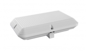
Application
- Wastewater treatment, oil and gas refineries, drilling rigs, petrochemical facilities, food and beverage facilities, tunnels, outdoor or indoor mounted general area lighting, and where flammable vapors, gases, ignitable dusts, fibers or flyings are present.
Standard
ATEX: EN IEC 60079-0-2018; EN 60079-7-2015; EN 60079-18-2015; EN 60079-31-2014;
Warning
ATEX :
- “WARNING – DO NOT OPEN WHEN ENERGIZED”;
- “WARNING – DO NOT OPEN WHEN AN EXPLOSIVE ATMOSPHERE IS PRESENT”;
- “WARNING – POTENTIAL ELECTROSTATIC CHARGING HAZARD – SEE INSTRUCTION”;
- End user shall use certified cable gland suitable type of protection for final installation purpose;
- The end user should be able to ensure that the product is not affected by the risk of static electricity.
- External earthing wire shall be connected when used and the cross-sectional area shall be more than 4mm²or 10AWG;
- Under rating condition, maximum temperature on the luminaire’s shell shall not be higher than 128℃ for T4.Temperature at cable inlet shall not be higher than allowable limit of the cable applied, to ensure the cable operation normally. The branch point is 51.4℃ and cable entry point is 47.3℃
Features
- Industry-leading efficacy: up to 140 lm/W
- -40°C to +40°C Ambient operating temperature
- Wide optics for uniform illumination
- 5 years warranty
- Entry Size: PG9
- Housing –Aluminum alloy (ADC12 )
- Lens – tempered glass
- Beam angle: 89°
- Dimension: 419×271×99mm
- Weight: 2.8kg
Parameters
- Power: 20W / 30W / 40W / 50W / 60W
- Input voltage: AC100-240/277V, 50/60Hz
- Power factor: 0.97
- Light efficacy: 120 - 140lm/W
- CCT: 3000K/4000K/5000K/5700K/6500K
- LEDs: 3030
- LED Driver: High efficiency LED Driver
Certificate & Standard
- II 2G Ex db eb IIC T4 Gb;
- II 2D Ex tb IIIC T 128°C Db;
- IP66;
- Certificate No:SEV 20 ATEX 0412X;
Mounting
Versatile mounting options:
- Pole mount
- Wall mount
- Ceiling mount
- U-bracket
- Drop mount
120W 150W 185W Explosion Proof Street Light - Class 1 Division 2 - Pole Mount
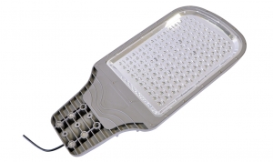
Key Benefit
- High Efficacy low decay SMD LED chip,up to 140lm/w @350ma, rated life span 100,000 hrs.
- High heat transmitting die cast housing with ADC12 aluminum, patented design, IP67 protection grade
- Shock and vibration resistant tempered glass, super clear 95% light transmit rate
- Anti-glare.Scientific optical reflector design, making the light more focus,even, comfortable for eyes
- Meanwell HLG series driver, the highest lever of Meanwell driver
- Surface treatment-Powder coating with Epoxy Polyester, salt resistant and chemical resistant, patented arc shape heat sink design, to prevent the dust from accumulating on the surface
- 2.0mm thick aluminum PCB with heat index 2.5, keep LED working under normal temperature
- EMC test standard, Total harmonic distortion (THD)<10%, minimize the impact towards electric system
Features
- Industry-leading efficacy: up to 140 lm/W
- -40°C to +40°C Ambient operating temperature
- Wide optics for uniform illumination
- 5 years warranty
- Entry Size: NPT 3/4”-14 ;
- Housing –Aluminum alloy (ADC12 );
- Lens – tempered glass
- Beam angle: 140° * 80°
- Dimension: 796x372x82mm
- Weight: 14.5kg
Parameters
- Power: Max 120W / 150W / 185W
- Input voltage: AC100-240/277V, 50/60Hz
- Power factor: 0.97
- Light efficacy: 120 - 140lm/W
- CCT: 3000K/4000K/5000K/5700K/6500K
- LEDs: 3030
- LED Driver: Meanwell HLG series
Certificate & Standard
Have certified CES-L fixtures with the NEC and CEC standards for hazardous location and environments
- Class I, Division 2, Groups A, B, C and D
- T-Class: T5
- Damp and wet locations
- Certificate No:E475887
Mounting
Versatile mounting options:
- Pole mount
How to install this explosion proof street light?
A.The mounting height around 12m (For example:150W), cantilever length of not more than a quarter of the mounting height , and the elevation should not exceed 15 °
B.Installation Step:
- Place the lamp cord into the pole
- Insert the lamp into the pole
- Adjust the lamp direction and fix screw into lock position
- Fixthe screw into lock position,the torque applied to the screw is 1.08 kg.m
- The size of cavity inserted into the junction box should not be more than 80mm*40mm*40mm
Seal the gaps between the power driver lid and the plate tightly with silicone glue.
60W 80W 100W Explosion Proof Street Light - Class 1 Division 2 - Pole Mount
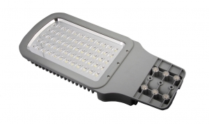
Key Benefit
- High Efficacy low decay SMD LED chip,up to 140lm/w @350ma, rated life span 100,000 hrs.
- High heat transmitting die cast housing with ADC12 aluminum, patented design, IP67 protection grade
- Shock and vibration resistant tempered glass, super clear 95% light transmit rate
- Anti-glare.Scientific optical reflector design, making the light more focus,even, comfortable for eyes
- Meanwell HLG series driver, the highest lever of Meanwell driver
- Surface treatment-Powder coating with Epoxy Polyester, salt resistant and chemical resistant, patented arc shape heat sink design, to prevent the dust from accumulating on the surface
- 2.0mm thick aluminum PCB with heat index 2.5, keep LED working under normal temperature
- EMC test standard, Total harmonic distortion (THD)<10%, minimize the impact towards electric system
Features
- Industry-leading efficacy: up to 140 lm/W
- -40°C to +40°C Ambient operating temperature
- Wide optics for uniform illumination
- 5 years warranty
- Entry Size: NPT 3/4”-14 ;
- Housing –Aluminum alloy (ADC12 );
- Lens – tempered glass
- Beam angle: 140° * 80°
- Dimension: 650x280x73mm
- Weight: 10kg
Parameters
- Power: Max 60W / 80W / 100W
- Input voltage: AC100-240/277V, 50/60Hz
- Power factor: 0.97
- Light efficacy: 120 - 140lm/W
- CCT: 3000K/4000K/5000K/5700K/6500K
- LEDs: 3030
- LED Driver: Meanwell HLG series
Certificate & Standard
Have certified CES-L fixtures with the NEC and CEC standards for hazardous location and environments
- Class I, Division 2, Groups A, B, C and D
- T-Class: T6
- Damp and wet locations
- Certificate No:E475887
Mounting
Versatile mounting options:
- Pole mount
How to install this explosion proof street light?
A.The mounting height around 12m (For example:150W), cantilever length of not more than a quarter of the mounting height , and the elevation should not exceed 15 °
B.Installation Step:
- Place the lamp cord into the pole
- Insert the lamp into the pole
- Adjust the lamp direction and fix screw into lock position
- Fixthe screw into lock position,the torque applied to the screw is 1.08 kg.m
- The size of cavity inserted into the junction box should not be more than 80mm*40mm*40mm
Seal the gaps between the power driver lid and the plate tightly with silicone glue.