Intrinsically Safe Explosion-proof System and Explosion-proof Certification
Part 1: Intrinsically Safe Explosion-Proof Technology
Intrinsically safe explosion-proof technology is currently the only technology that has been standardized for Zone 0. For automatic instruments, the commonly used explosion-proof forms are intrinsically safe, flameproof and increased safety. However, due to the rapid development of electronic technology and the continuous birth of low-power electronic devices, the promotion and application of intrinsically safe explosion-proof technology has a wider space. Especially since the intrinsically safe (also called "intrinsically safe") explosion-proof form compared with other explosion-proof forms not only has a simple structure, a wide range of applications, but also has the characteristics of easy operation and maintenance, so this kind of suppression ignition source Intrinsically safe explosion protection with energy as the means of explosion protection has been accepted by instrument manufacturers and users.
-
The basic principle of intrinsically safe explosion-proof technology
Electrical sparks and thermal effects are the main sources of ignition for explosive hazardous gas explosions. Intrinsic safety is achieved by limiting the energy of two possible ignition sources, sparks and thermal effects. Under normal working and fault conditions, when the energy of the spark or thermal effect that the meter may generate is less than this energy, the low-level meter cannot ignite the explosive dangerous gas and cause an explosion. The principle is to start with limiting energy, and reliably limit the voltage and current in the circuit within an allowable range, so as to ensure that the electric spark and thermal effect generated by the instrument in the case of normal operation or faults such as short circuit and component damage will not cause damage. Causes an explosion of hazardous gas that may be present around it.
-
Characteristics of intrinsically safe explosion-proof technology
Intrinsically safe explosion-proof technology is actually a low-power design technology. Usually for hydrogen (ⅡC) environment, the circuit power must be limited to about 1.3W. It can be seen that the intrinsically safe technology can be well applied to industrial automation instruments.Compared with any other explosion-proof type, the use of intrinsically safe explosion-proof technology can bring the following technical and commercial characteristics to industrial automation instruments.
- It is not necessary to design and manufacture a flame-proof enclosure with a complex, bulky and cumbersome enclosure. Therefore, the intrinsically safe instrument has the characteristics of simple structure, small size, light weight and cost. According to the data, the ratio of the cost of establishing an intrinsically safe and flameproof switch transmission circuit is about 1:4.
- Maintenance, calibration and replacement of some parts of the instrument can be carried out under live conditions.
- High safety and reliability. The intrinsically safe instrument will not reduce the safety and reliability of the instrument due to man-made reasons such as loss of fastening bolts or corrosion and scratches on the joint surface of the casing.
- Since the intrinsically safe explosion-proof technology is a "weak current" technology, the use of intrinsically safe instruments can avoid the occurrence of electric shock casualties for on-site engineering and technical personnel.
- a wide range of applications. Intrinsically safe technology is the only explosion-proof system that can be used in zone 0 hazardous locations.
- For simple devices such as thermocouples, it can be connected to the intrinsically safe explosion-proof system without special certification.
- In summary, for automated instruments, intrinsically safe explosion-proof technology is an ideal explosion-proof technology, and it will also be widely used in the design of fieldbus intelligent instruments and their systems
3. Intrinsically safe equipment and related equipment
There are two types: intrinsically safe electrical equipment and associated equipment.
1). intrinsically safe electrical equipment
Under the conditions specified in the standard (including normal operation and specified fault conditions), any electrical sparks and thermal effects generated cannot yet ignite the specified explosive gas atmosphere electrical equipment. It can be used in hazardous locations. It can be divided into general intrinsically safe electrical equipment and simple electrical equipment. General intrinsically safe electrical equipment: It has an energy storage element and is an intrinsically safe electrical equipment that requires explosion-proof certification, such as transmitters, proximity switches, etc.
Simple electrical equipment: According to the manufacturer's technical conditions, electrical equipment whose electrical parameter values do not exceed 1.2V, <0.1A, <25mW, <20uJ, they do not need explosion-proof certification. Can be freely configured in intrinsically safe circuits. Such as: resistance (including variable resistance), light-emitting diodes, switches, thermocouples, thermal resistance, strain gauges.
2) Associated equipment (safety barrier):
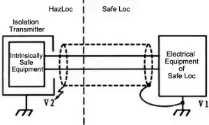
an electrical equipment installed in a safe place and connected between intrinsically safe electrical equipment and non-intrinsically safe electrical equipment.
The safety barrier can limit the energy that enters the intrinsically safe equipment on site within a safe value, thereby ensuring the safety of field equipment, personnel and production.
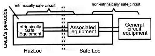
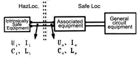
The schematic diagram of the intrinsically safe system circuit is as follows:
-
Classification of intrinsically safe electrical equipment
- Category: Based on the classification principles of electrical equipment stipulated in the standard GS3836.1 "General Requirements for Electrical Equipment for Explosive Gas Environments Part 1", intrinsically safe instruments can be divided into two categories:
Class I: Intrinsically Safe Instruments for Coal Mine (mining industry)
Class II: intrinsically safe instruments for factories (surface industry) Class II intrinsically safe instruments for factories, like gas groups, can be further divided into three levels: A, B, and C.
- Levels: Intrinsically safe instruments and related equipment can be divided into two levels, ia and ib, according to the safety level of the 4 places where they are used or the connected places.
Class ia means that the explosive gas mixture cannot be ignited under normal operation, one count failure and two count failures. That is to say, the ia-level instrument will not cause a safety failure under the condition of considering two count faults.
Class ib means that an explosive gas mixture cannot be ignited under normal operation and a count failure. Obviously, the safety level of the IA-level instrument is higher than that of the IB-level instrument. The IB-level instrument only considers that a safety failure will not occur when the instrument has one fault, but if the instrument has the first count failure, it may occur. Therefore, the safety level of the ib-level intrinsically safe instrument is worse than that of the ia-level instrument, and it is only suitable for zone 1 and zone 2 dangerous places like the explosion-proof and increased safety type instruments. Correspondingly, Class ib intrinsically safe related equipment can be connected to intrinsically safe instruments or equipment in Zone 1 and Zone 2 hazardous locations. The ia-level intrinsically safe instrument can be used in the hazardous area of zone 0 with high hazard level; the ia-level intrinsically safe related equipment can be connected with the intrinsically safe instrument or equipment in the 0-zone hazardous area. Class ia intrinsically safe equipment is the one with the highest degree of safety among all explosion-proof types.
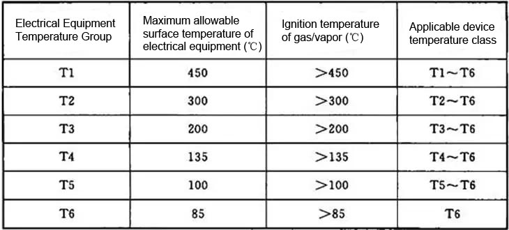
- Equipment temperature grade: The equipment temperature grade specifies the high allowable temperature value on the surface of the equipment. This is mainly based on technical and economic considerations. In most cases, the purchase and safety costs of equipment with lower temperature levels are higher when working. By comparison, the selection of intrinsically safe equipment will be more effective and economical. Intrinsically safe equipment installed directly in a hazardous location requires consideration of the equipment temperature rating, while associated equipment does not need to perform the equipment temperature rating section. The temperature level of the equipment must be lower than that used in the hazardous location environment
-
Explosion-proof mark:
The explosion-proof mark of the intrinsically safe instrument is the same as the explosion-proof mark of other explosion-proof types. It is essentially the code name of the explosive hazardous place for the instrument.
Usually an explosive hazardous area needs to be defined by three parameters.
1) Hazardous location area It reflects the frequency or duration of the possible occurrence of dangerous gas, that is, the degree of danger of explosion.
2) The type of hazardous gas, that is, the gas group considers the ignition energy of the possible hazardous gas.
3) The ignition temperature of the dangerous gas, that is, the ignition temperature of the dangerous gas that may appear in the gas temperature group.
Correspondingly, the explosion-proof mark of the intrinsically safe instrument must also express the three parameters of the applicable area, gas group and temperature group in turn after the "Ex" explosion-proof mark. Explosion-proof mark for intrinsically safe electrical equipment.
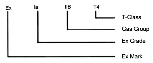
For example, the explosion-proof mark ExdIIBT4 indicates that the intrinsically safe equipment can be applied to the hazardous area of Zone 0 where the gas group is not higher than Class II Class B, and the gas ignition temperature is not lower than T4 (135°C). Associated equipment (safety barrier) explosion-proof mark.
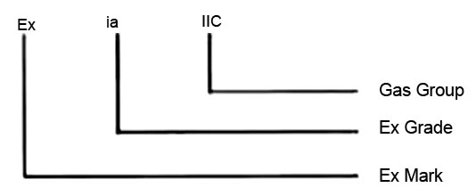
For example, the explosion-proof mark [Exia]IIB indicates that the safety barrier can be applied to the hazardous area of zone 0 whose gas group is not higher than Class II Class B.
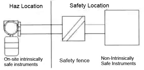
Part. 2 The basic composition of the intrinsically safe system
The intrinsically safe system is a circuit system that achieves electrical explosion-proof by limiting electrical energy, and does not restrict the use of places (where the ia level is applicable to dangerous places in Zone 0, Zone I, and Zone II) and explosive The type of gas mixture (limited to include all flammable gases); with a high degree of safety, maintainability and economy. A schematic diagram of an intrinsically safe system.
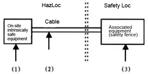
-
On-site intrinsically safe equipment
Considering the energy storage elements of field equipment, the field equipment in the explosive gas hazardous environment should be designed according to the requirements of intrinsically safe explosion-proof, and phase limiting measures should be taken for the circuits of the energy storage elements such as inductors and capacitors included in them, and reduce them as much as possible. At the same time, the power consumption and temperature rise of the circuit components are considered to ensure that the equipment will not be ignited by sparks and heat sources whether it is in normal operation or in a fault state. That is, the field device must be an intrinsically safe device. On-site intrinsically safe equipment has the main parameters of intrinsically safe performance:
Maximum Input Voltage (Ui): The highest voltage (peak AC or DC) that can be applied to an intrinsically safe circuit connection device without invalidating the intrinsically safe performance.
Maximum Input Current (Ii): The highest current (peak AC or DC) that can be applied to an intrinsically safe circuit connection without invalidating the intrinsically safe performance.
Maximum input power (Pi): The maximum input power of an intrinsically safe circuit that may be dissipated inside the electrical equipment when the electrical equipment is connected to an external power source without invalidating the intrinsically safe performance.
Maximum Internal Equivalent Capacitance (Ci): The total equivalent internal capacitance of electrical equipment that occurs through the electrical equipment connecting device.
Maximum Internal Equivalent Inductance (Li): The total equivalent internal inductance of electrical equipment that occurs through the electrical equipment connecting device.
-
Connect the cable
From the perspective of system wiring engineering, due to the distributed capacitance and distributed inductance of the connecting cable, the connecting cable becomes an energy storage element. They inevitably store energy in the process of signal transmission. Once the line is open or shorted, the stored energy will be released in the form of electrical sparks or thermal effects, affecting the intrinsic safety performance of the system. Therefore, it is necessary to ensure that the connection transmission cable will not be affected by external electromagnetic field interference and mixed with other circuits, but also to limit the wiring length and the additional non-intrinsically safe energy caused by the induced electromotive force, so as to determine the allowable distributed capacitance and allowable distribution of the cable. Inductance, explosion-proof inspection agencies all over the world mainly take the method of considering the cable distribution parameters in the way of centralized parameters.
The basic parameters of the intrinsic safety performance of the connecting cable are as follows:
The maximum allowable distributed capacitance of the cable (Ci): (Cc)=(Ck)*L
Maximum allowable distributed inductance of the cable (Lc): (Lc)=(Lk)*L
Remarks:
In the formula, Ck -- distributed capacitance per unit length of cable.
Lk -- distributed inductance per unit length of cable.
L -- actual wiring length
-
Associated equipment - safety barrier
From the perspective of equipment configuration in the control room, this part of the electrical circuit must be capable of suppressing the energy transmitted from the non-intrinsically safe circuit in the safe place to the intrinsically safe equipment in the dangerous place to the ignition limit regardless of whether the system is in normal working state or in a fault state. (small ignition energy) the following protection function.
The basic parameters of the intrinsic safety performance of the safety barrier:
High voltage (AC RMS or DC Um): High voltage applied to non-intrinsically safe connections of associated equipment without invalidating the intrinsically safe performance.
Maximum output voltage (Uo): The high output voltage (peak AC or DC) of an intrinsically safe circuit that may occur in an open circuit condition when the equipment connection device is powered up to high voltages (including Um and Ui).
Maximum input current (Io): High current (peak AC or DC) from intrinsically safe circuits of electrical equipment connections.
Maximum input power (Po): The high power of intrinsically safe circuits that can be obtained from electrical equipment.
Maximum external capacitance (Co): The bulk capacitance of an intrinsically safe circuit that can be connected to electrical equipment connections without invalidating the intrinsically safe performance.
Maximum External Inductance (Lo): The large inductance of an intrinsically safe circuit that may be connected to electrical equipment connections without invalidating the intrinsically safe performance.
-
Intrinsic safety system combination conditions
In order to ensure the safe and normal use of the equipment, each configuration room of the intrinsically safe system must meet the following conditions.
- The explosion-proof mark level of the on-site intrinsically safe equipment cannot be higher than the explosion-proof mark level of the safety barrier.
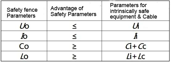
- The following inequalities must be met between the associated equipment, the field intrinsically safe equipment and the parameters of the connecting cable.
Part 3 General requirements for the design of intrinsically safe systems
- Principles for selection of intrinsically safe system configuration equipment
The intrinsically safe system consists of intrinsically safe field equipment, associated equipment (also called safety barriers) and connecting cables. In terms of intrinsically safe explosion-proof performance, they must satisfy Uo≤Ui, Io≤Ii , Po≤Pi, Co≥Cc+Ci and Lo≥Lc+Li four conditions.
The selection principles for these device configurations are:
1) Principles for selection of intrinsically safe electrical equipment
Simple equipment: According to the GB3836.4-2010 explosion-proof standard, electrical equipment whose voltage does not exceed 1.2V, current does not exceed 0.1A, and whose energy does not exceed 20μJ or power does not exceed 25mW can be regarded as simple equipment, among which common instruments The equipment includes thermocouples, thermal resistances, pH electrodes, strain gauges and switches, etc. Their typical characteristics are that the internal equivalent inductance Li=0 and the internal equivalent capacitance Ci=0 of the instrumentation equipment. Intrinsically safe electrical equipment: For field equipment installed in hazardous locations, the following issues must be clarified:
a) Whether the intrinsically safe electrical equipment has been designed in accordance with the requirements of GB3836.1-2010 and GB3836.4-2010 and has been approved by explosion-proof inspection agencies
c) Whether the level specified by the explosion-proof mark is suitable for the safety requirements of the hazardous location used
d) clear Ui, Ii, Pi, Ci, and Li parameters
e) Whether the intrinsically safe circuit is grounded or whether the intrinsically safe circuit of the grounding part is effectively isolated from the circuit of the interface part of the safety barrier.
f) in what way the signal transmission is carried out; f), the low working voltage of the intrinsically safe electrical equipment and the normal working current of the loop.
g) On the basis of the above questions, select the corresponding safety barrier.
2) The selection principle of safety barrier
- The explosion-proof mark of the safety barrier must not be lower than the level of the explosion-proof mark of the intrinsically safe field equipment.
- Make sure that the terminal resistance and loop resistance of the safety barrier can meet the low working voltage of the intrinsically safe field equipment.
- The intrinsically safe end safety parameters of the safety barrier can meet the requirements of Uo≤Ui, Io≤Ii, Po≤Pi, Co≥Cc and Lo≥Lc.
- Select a safety barrier that matches the power supply polarity and signal transmission mode of the intrinsically safe field instrument.
- to avoid the leakage current of the safety barrier affecting the normal operation of the intrinsically safe field equipment.
- There are two types of safety barriers, one is Zener safety barrier and the other is isolated safety barrier.
3) Selection principle of connecting cable
The connecting cable used to connect the intrinsically safe field equipment and the safety barrier in the intrinsically safe system, its distribution parameters determine the rationality and scope of use of the intrinsically safe system to a certain extent, so it must meet the following conditions .
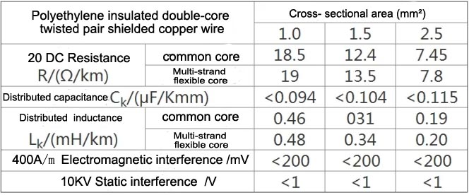
- Specification of connecting cable: the connecting cable is copper core stranded wire, and the cross-sectional area of each core wire is not less than 0.5mm2.The dielectric strength should be able to withstand 2 times the rated voltage of the intrinsically safe circuit, but not lower than the withstand voltage test of 500V.
- Limitation on the length of the connecting cable: In the intrinsically safe system, both the on-site intrinsically safe instrument and the connecting cable are the loads of the safety barrier. When the safety barrier and the on-site intrinsically safe instrument are selected, the length of the connecting cable is determined. The specific method is as follows.
Calculate the maximum external distribution parameters of the cable according to the formulas of Co≥Cc-Ci and Lc≤Lo-Li; calculate the cable length according to the formulas of L=Cc/Ck and L=Lc/Lk respectively, and take the smaller value of the two as the actual distribution The line length L, but the multi-core cable, should consider the mutual superposition effect. At present, many domestic cable manufacturers have produced special cables for intrinsic safety designed for intrinsically safe systems. For the convenience of comparison and selection, the following table 1 shows the distribution parameters of typical ordinary connecting cables, and table 2 shows typical domestic cables. Install special cable distribution parameters for reference.
Table 1 Distribution parameters of typical ordinary cables
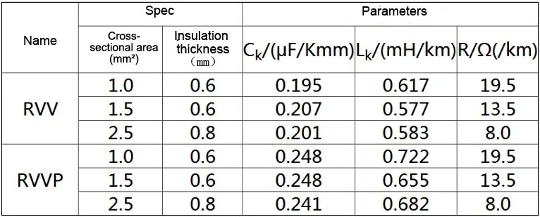
RVV: Copper core PVC insulated and sheathed flexible wire RVVP: Copper core PVC insulated, metal shielded and sheathed flexible wire table
Table 2 Distribution parameters of special cables for typical domestic intrinsically safe instruments
-
Optimized configuration of intrinsically safe system
To achieve the optimal configuration of the intrinsically safe system, the above-mentioned links should be considered as a whole. From the perspective of intrinsically safe circuit design and the analysis of actual use, the distribution parameters of cables are the main factors affecting the application of intrinsically safe systems. In order to improve the allowable cable distribution parameters of the system, it can be achieved by increasing the allowable external parameters of the safety barrier and reducing the internal equivalent parameters of the intrinsically safe equipment.
1) To improve the allowable external parameters of the safety barrier, it can be achieved by optimizing the analysis, selecting the safety barrier reasonably, and trying to choose the safety barrier with lower high open-circuit voltage and large short-circuit current.
2) To reduce the internal equivalent parameters of the intrinsically safe instrument, it can usually be accomplished by the same method as the above-mentioned restraining the energy storage of the capacitor and inductance in the circuit of the intrinsically safe instrument. However, in practice, there is a more effective way to suppress the input capacitance of the intrinsically safe instrument, that is, to add two series-connected forward diodes to the input end of the intrinsically safe instrument, and seal them together with the entire intrinsically safe circuit. The application of this method not only makes the intrinsically safe instrument have the function of reverse polarity protection, but also reliably blocks the discharge circuit of the internal capacitance of the intrinsically safe instrument to the circuit due to the function of the double diode, which fundamentally avoids the internal safety of the instrument. The influence of the capacitance on the external circuit, at this time, the internal equivalent capacitance of the instrument can be approximately considered to be zero, that is, Ci=0, which greatly improves the allowable cable distributed capacitance of the intrinsically safe system. At this time, Cc=Co.
-
On-site wiring principle of intrinsically safe system
1) The wiring of the whole system must be composed of the system approved by the inspection agency.
2) Be careful to avoid the mixed contact between the intrinsically safe circuit and the non-intrinsically safe circuit.
3) The intrinsically safe cables and non-intrinsically safe cables from the control room to the site are laid in their respective wiring troughs, separated by partitions in the middle, and the wiring troughs are covered to prevent damage from external mechanical operations.
4) The cables from the on-site junction box or the wiring trough to the intrinsically safe instrument are laid in the steel pipe to prevent mechanical damage and the danger caused by electromagnetic induction.
5) Intrinsically safe cables and non-intrinsically safe cables do not share a metal conduit and the same field junction box.
6) The connecting cables and their steel pipes and terminal boards should have blue marks (or blue tapes) for easy identification.
7) The grounding bus bar and grounding device of the Zener-type safety barrier must meet the requirements of the safety barrier's instruction manual and relevant electrical safety regulations.
8) Multiple intrinsically safe circuits or associated circuits should not share the same cable (except for those with shielded cable cores) or co-locate in the same steel pipe (except for shielded conductors).
-
Safety barrier selection
There are two main types of safety barriers: zener barriers and isolation barriers.
Zener-type safety barrier: The Zener-type safety barrier adopts a series of fast fuses, current-limiting resistors and parallel voltage-limiting Zener diodes in the circuit loop to achieve energy limitation to ensure the safety of the signal connection between the instrument in the dangerous area and the instrument in the safe area. limited energy. It uses very few devices, small size and low price, but it also has some fatal defects, so that the scope of application is greatly limited. There is currently a significant downward trend.
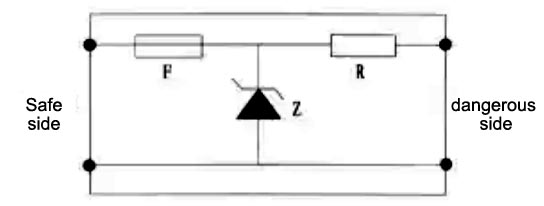
Schematic diagram of the principle of Zener safety barrier
- When using a Zener-type safety barrier, the factory must have a special intrinsically safe grounding system, and the grounding resistance of the intrinsically safe circuit must be less than 1Ω.
- When using Zener-type safety barrier, the on-site intrinsic safety meter in the dangerous area must be of the isolation type, and the non-isolated type of meter cannot be used.
- The use of a zener safety barrier has a very large response to the power supply voltage. The fluctuation of the power supply voltage may cause the current leakage of the Zener diode, which will cause signal errors or send out wrong levels. In severe cases, the fast fuse will burn. If it is broken and damaged for a long time, the internal Zener tube, current limiting resistor and fuse of the Zener safety barrier are encapsulated as a whole according to the regulations. Once damaged, it cannot be repaired.
- When using a zener-type safety barrier, the negative pole of the signal must be connected to the intrinsically safe grounding, which greatly reduces the anti-interference ability of the system signal and affects the reliability of the system, especially for the DCS system.
Isolated safety barrier
The isolated safety barrier not only has limited energy function, but also has isolation function. It is mainly composed of loop energy limiting unit, signal, power isolation unit and signal processing unit. Its basic functional block diagram is as follows:
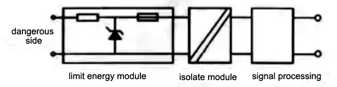
It includes two categories of independently powered isolation barriers and loop powered isolation barriers.
- Compared with the zener safety barrier, the isolated safety barrier is more expensive, but its many advantages and features still bring a lot of convenience to users, making more and more users prefer to choose the isolated safety barrier.
- The use of isolated safety barriers can effectively isolate the field loop signal in the dangerous area and the loop signal in the safe area. In this way, the intrinsically safe automatic control system does not need an intrinsically safe grounding system, which simplifies the construction when the intrinsically safe explosion-proof system is applied.
- The use of isolated safety barriers greatly enhances the anti-interference ability of detection and control loops and improves system reliability.
- use an isolated safety barrier, allow the field instrument to be grounded, and allow the field instrument to be non-isolated.
- the isolated safety barrier has many protection function circuits, the possibility of accidental damage is small, and the field instrument is allowed to be overhauled with electricity. This shortens project start-up preparation time and reduces downtime.
- the isolated safety barrier has strong signal processing capability. Such as switch input state control, mV, Pt100 becomes 4 ~ 20mA and so on. This provides greater convenience, rationality and effectiveness for the application of field instruments and control systems.
- When the user applies DCS and ESD at the same time, choose a safety barrier with one entry and two exits, which can effectively isolate the two systems and avoid mutual influence between the systems. h) The loop-powered isolation barrier not only maintains the advantages of the active isolation barrier, but also has the same wiring convenience as the Zener barrier. It does not require another 24V power supply, and is especially suitable for DCS with I/O card power supply directly. system.
5. Grounding Analysis of Safety Barrier
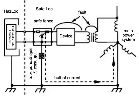
If the zener barrier is not grounded, as shown below. If a high-to-ground potential (phase line of AC 220V) falls on the safety barrier in the power distribution fault wire in the safe area, the zener tube only limits the voltage U0 between the conductors of the zener safety barrier, but cannot limit any one-line pair The potential of the ground is introduced into the dangerous area. Once the insulation isolation of the field instrument to the ground is not good, a short circuit occurs to the ground, and a strong ground current is immediately generated. Such a high potential and the energy of the ground current are not limited. Therefore, Very reliable sparks can be dangerous.
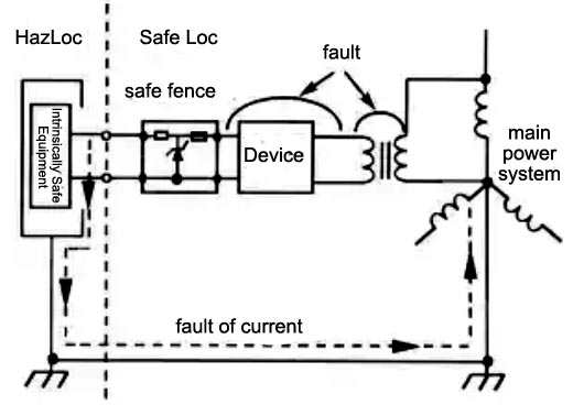
If the safety barrier is reliably grounded, as shown below, when the same fault occurs, the Zener tube limits the potential to the ground, and the fault current can only flow in the safe area, thus ensuring the site safety of the dangerous area. This grounding is also called "intrinsically safe grounding".
This is the case with an isolated barrier
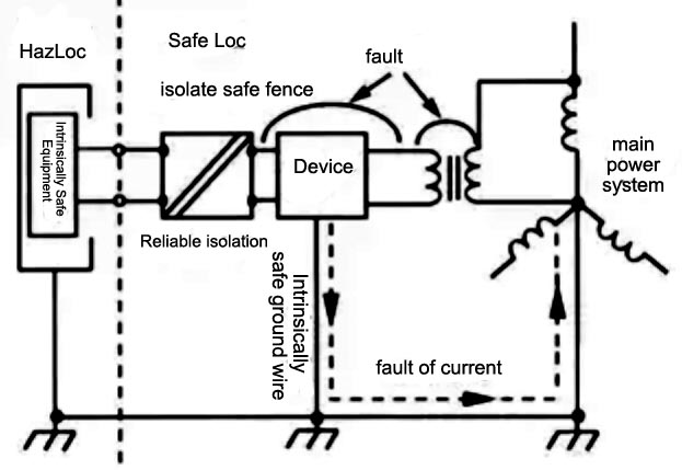
When a fault occurs, since there is a reliable isolation unit in the isolated safety barrier, it generates a potential to the ground, but the ground current cannot flow from the reliable isolation unit to the dangerous area, so there is no need for a special circuit on the intrinsically safe circuit side of the safety barrier. Secure grounding, as long as the general requirements are followed. If a shielded cable is used, the shielding of the cable can be grounded on the field instrument side or the control room side.
Part 4 Intrinsically Safe System Certification
- Certification standards and certification bodies
Certification standards: Standard GB3836.1-2000 "Electrical Equipment for Explosive Gas Atmospheres - Part 1: General Requirements (eqv IEC 60079-0: 1998)" and GB3836.4-2000 "Electrical Equipment for Explosive Gas Atmospheres - Part 4: Essential Safety "i" (eqv IEC 60079-11:1999)" standard is equivalent to the IEC 60079 standard, which was released on 2000-10-17 and implemented on 2001-06-01, replacing the original GB3836.1983 standard.
Certification bodies and certification marks: The Explosion-Proof Supervision and Inspection Station for Instrumentation (NEPSI) is the focal point for the safety supervision, inspection and accreditation of domestic and imported explosion-proof products of instruments. And obtained mutual recognition of explosion-proof certification technology with the American Factory Research Council (FMRC) and the German Federal Institute of Physics and Technology (PTB) respectively (see website WWW.NEPAI.COM).


- Intrinsic safety system certification
The verification and approval of the intrinsically safe system involves on-site intrinsically safe equipment, associated equipment and their wiring. At present, there are no strict regulations on the approval of intrinsically safe explosion-proof systems in the world, that is, different methods, different regions, different manufacturers, and even different products are adopted. But to sum up, there are mainly two kinds of approval methods, namely system approval and parameter approval.
1) Intrinsically Safe System Approval
System Approval (System Approva1) is an authentication method in which an explosion-proof inspection agency identifies a specific field instrument with a specific safety barrier, and at the same time gives the distributed capacitance and distributed inductance of the cable in the form of centralized parameters. This kind of approval work is often based on circuit analysis verification or necessary spark ignition test, and confirms the rationality and safety of the system composed of specific intrinsically safe equipment and related equipment, and the inspection agency issues relevant written documents (usually called Joint forensics for explosion protection).
The block diagram of the intrinsic safety system certification is as follows:
In the system approval method, the combination matching relationship is clear, the system verification is qualified, the user selection is simple, and the overall explosion-proof performance is easy to guarantee, but the combination flexibility is poor.
1) Approval of intrinsically safe system parameters
Parameter approval is a method of specifying the safety parameters of the intrinsically safe equipment and related equipment to be approved, and then evaluating the safety performance separately, and then connecting the intrinsically safe equipment and the related equipment according to the principle of safety parameter matching. This verification and accreditation method based on the safety rating of the equipment itself is currently more popular in Europe and the United States, and may become a common international accreditation method. The accreditation relationship is as follows.
In the parameter approval method, the intrinsically safe equipment and the associated equipment are first "considered" to be disconnected, and their safety parameter ratings are specified at their respective terminals.
Among them: For intrinsically safe equipment installed in hazardous locations, the following safety parameters are given: Ui, Ii, Pi, Ci and Li.
For the associated equipment installed in a safe place, the following safety parameters are given as Uo, Io, Po, Co and Lo.
Then imagine two separate failures for the intrinsically safe equipment and the associated equipment. The so-called safety parameter rating is the maximum rating of the instrument to maintain the safety performance. Based on this rating, the intrinsic safety performance of the intrinsically safe equipment is evaluated. When the above safety parameters are approved, the cable distribution parameters can be obtained according to the following formula: Cc≤Co-Ci Lc≤Lo-Li.
In the parameter approval method, the intrinsically safe equipment and related equipment should be approved respectively, and the qualified equipment marked with their respective numbers should be approved. Labels, and the system constituted by this, the certificate numbers of the two are different. The great advantage of parameter approval is that the user can freely choose and realize the combination of the intrinsic safety system.
As long as the user masters the rated values of their respective safety parameters, and according to the matching conditions to ensure the safety performance, they can construct the intrinsic safety system by themselves (see this manual). combination conditions of the safety system). No matter which of the above methods is adopted for the certification of intrinsically safe systems, in addition to considering the three elements of the inspection system: intrinsically safe field instruments, connecting cables and related equipment, it should also take into account its structural characteristics, whether it is grounded, the impedance of secondary instruments, etc. Considering.
At present, the main accreditation method adopted explosion-proof inspection agencies is still essentially the "system accreditation" method, that is, the "joint forensics" method, and is gradually advancing in the direction of "parameter accreditation". During the verification and approval of related equipment, four parameters are given in the approval document: high open circuit voltage Uo, large short circuit current Io, maximum allowable external capacitance Co and maximum allowable external inductance Lo. When the verification and approval of intrinsically safe equipment is carried out, the model specifications (which can be one or more) of the associated equipment to be used and the cable distribution parameter values allowed by the system are also specified in the approval document. On the above, the intrinsic safety system equipment determined by considering the mutual system matching ensures the explosion-proof safety performance of the entire system.